解码器的Verilog代码
此项目是解码器的Verilog代码。解码器是数字电路中的主要组合组件之一。 解码器主要用于存储器地址解码和数据多路分解。在此Verilog项目中,提供了用于解码器的Verilog代码。 解码器用于内存地址解码。了解更多请下载附件。
应用介绍
此项目是解码器的Verilog代码。
解码器是数字电路中的主要组合组件之一。 解码器主要用于存储器地址解码和数据多路分解。在此Verilog项目中,提供了用于解码器的Verilog代码。 解码器用于内存地址解码。
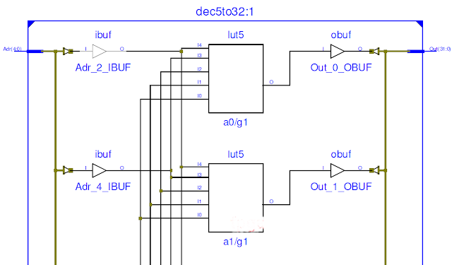
下图所示的解码器对输入的5位地址进行解码,并输出32位信号以选择要写入存储器的地址。 为了设计解码器,使用了32个5输入与门。

本人在下方展示了一小段的5至32个解码器的Verilog代码;想了解更多请下载附件。
// fpga4student.com: FPGA projects, Verilog projects, VHDL projects
// Verilog code for decoder
// 5-input AND gate
module AND_5_input(g,a,b,c,d,e);
  output g;
  input a,b,c,d,e;
  and #(50) and1(f1,a,b,c,d),
            and2(g,f1,e);
endmodule
// fpga4student.com: FPGA projects, Verilog projects, VHDL projects
// Verilog code for decoder
// Decoder top level Verilog code using 5-input AND gates
module dec5to32(Out,Adr);
input [4:0] Adr; // Adr=Address of register
output [31:0] Out;
not #(50) Inv4(Nota, Adr[4]);
not #(50) Inv3(Notb, Adr[3]);
not #(50) Inv2(Notc, Adr[2]);
not #(50) Inv1(Notd, Adr[1]);
not #(50) Inv0(Note, Adr[0]);
AND_5_input a0(Out[0],  Nota,Notb,Notc,Notd,Note); // 00000
AND_5_input a1(Out[1],  Nota,Notb,Notc,Notd,Adr[0]); // 00001
AND_5_input a2(Out[2],  Nota,Notb,Notc,Adr[1],Note); //00010
AND_5_input a3(Out[3],  Nota,Notb,Notc,Adr[1],Adr[0]);
AND_5_input a4(Out[4],  Nota,Notb,Adr[2],Notd,Note);
AND_5_input a5(Out[5],  Nota,Notb,Adr[2],Notd,Adr[0]);
AND_5_input a6(Out[6],  Nota,Notb,Adr[2],Adr[1],Note);
AND_5_input a7(Out[7],  Nota,Notb,Adr[2],Adr[1],Adr[0]);
AND_5_input a8(Out[8],    Nota,Adr[3],Notc,Notd,Note);
AND_5_input a9(Out[9],    Nota,Adr[3],Notc,Notd,Adr[0]);
AND_5_input a10(Out[10],  Nota,Adr[3],Notc,Adr[1],Note);
AND_5_input a11(Out[11],  Nota,Adr[3],Notc,Adr[1],Adr[0]);
..........................................................................
©版权声明:本文内容由互联网用户自发贡献,版权归原创作者所有,本站不拥有所有权,也不承担相关法律责任。如果您发现本站中有涉嫌抄袭的内容,欢迎发送邮件至: www_apollocode_net@163.com 进行举报,并提供相关证据,一经查实,本站将立刻删除涉嫌侵权内容。
转载请注明出处: apollocode » 解码器的Verilog代码
文件列表(部分)
| 名称 | 大小 | 修改日期 |
|---|---|---|
| 解码器的Verilog代码(附件).txt | 0.62 KB | 2020-04-05 |
| d1.png | 25.45 KB | 2020-04-05 |
| image | 0.00 KB | 2020-04-05 |


发表评论 取消回复